Share
Pin
Tweet
Send
Share
Send
Lamps.
But here I must say, lucky! Previously, I came across only discharge indicators, for the supply of which, take out and put 180V! Everything is very convenient here, you can use 5V power supply (strictly speaking, no more than 4.5V, but more on that later), i.e. the same line that is used to operate the main circuits.
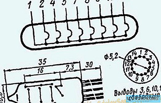
The lamp is a bulb with a vacuum, in which eight filaments are located. Thus, the IV-9 has a common conclusion, and eight segment ones. To output any information, it is necessary to “feed” the general and corresponding segment conclusions. The polarity of the connection does not matter. In my case, I connected pin 1 to the power plus (the supply voltage, in my circuit, is changed to adjust the brightness of the lamps) and connected the segment leads to ground.

Now about the lamp control. The customer insisted on a static indication, therefore, we will have a bunch of control signals (7 outputs * 4 lamps). To increase the number of pins, I applied four 74HC595 shift registers, the pins of which are connected to four ULN2003 microcircuits. The ULN2003 chip is a set of seven transistor switches. Each transistor switch has a limiting resistor in its base, so you can safely hook the outputs from the shift register directly to the control inputs of the uln.
Scheme.
The main workhorse is mega8. Her job is to interrogate either the temperature sensor - DS18B20 or the DS1307 real-time clock and output information to the lamps by writing the necessary array to the shift registers. Also, when one of the four buttons is triggered, the corresponding digit in hours or minutes changes. Seconds when changing hours or minutes are reset. By pressing the first and fourth buttons simultaneously, the device enters the temperature display mode. Details, you can watch the video. All four buttons "sit" on one interrupt, after which it is determined which button is pressed, here is an example of such an implementation:

Device Diagram:

This is the first part of the work, on which there is no brightness control for the lamps - they are on "full". All device power is 5V. In this version, the clock can be powered even from a USB port! The lamps are also not shown on the diagram, to connect them you need to connect their anodes to the power plus, and connect the segment leads through current-limiting resistors (the segment current should not exceed 19 mA) to the terminals L (1) _1 .... L (4) _7. When adjusting the brightness, the anodes of the lamps and the conclusions of number 9 of the ULN2003 chips are connected not to the power plus, but to the output of the power control circuit.
Scheme for adjusting the brightness:

At the input (INPUT +; INPUT-) we apply a constant voltage of 7-9V. Linear stabilizer 7805 stabilizes the voltage up to 5V, which is used to power the microcontroller, real-time clock, shift registers and temperature sensor.
LM317 Linear Stabilizer - Used to implement dimming. At the values of R1-3.9kOhm, and RS_1, RS-2, the variable resistor by 10kOhm, the voltage 5V_ADJ_OUT will change depending on the resistance of the variable resistor from 2.5 to 4.9V. On the LM317 you need to put a small radiator, in literally 10 minutes I did the same as in the photo, which copes well with cooling. Material is a small part of the cd-rom case:

The photo shows the output of the temperature sensor and the battery compartment for the DS1307 real-time clock.
Now execution.
Case:

I lengthened the conclusions from the lamps and wound them into pigtails and returned them to their original place:

Control board (attached to the "native" places):


Board mounting and lamp connection:

As a result:


Download firmware and boards:
Attention! You do not have permission to view hidden text.
Share
Pin
Tweet
Send
Share
Send