Types of winding connections
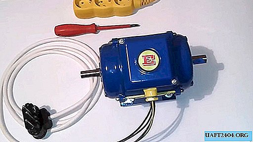
The three-phase motor contains a stator - a fixed part with fixed wire coils. They are offset relative to each other in a circle by 120 angular degrees. The alternating current passing through the windings creates a changing magnetic field, pushing the movable part of the motor - the rotor, or as they called it before - the armature.
There are two ways to turn on the windings among themselves:

- Star - the first ends of the windings are interconnected, and the phase conductors of the network are connected to the second leads of the coils.
- Triangle - coils are connected sequentially one after another, the end of the third winding is connected to the beginning of the first. Schematically form a triangle, to the vertices of which the phases are connected.

Stages of the work:
1. Having carefully examined the electric motor, find a socket (usually an aluminum plate) with information about the parameters. No need to tackle the alteration of a motor with a power of more than 1 kW (1kW). The inscription DY 220/400 means that the motor can be turned on both according to the "triangle" (D) and the "star" (Y). The operating voltage is 220 volts single / or 400 three-phase. Terminals marked L (1 ÷ 3) for phase connection.
2. As a standard, the coils of a 3-phase electric motor are switched on by a "star". Changing the position of the strip jumpers will create a triangle pattern.
3. After that, L1 is connected to the phase conductor, and on L3 - the neutral wire. We connect the middle terminal (L2) to a bias capacitor, the second terminal of which is connected to phase or zero. This determines the direction of rotation of the armature. A motor power of 100 W will require a capacitance of 8 ÷ 10 μF, for 0.25 kW a capacitor of 20 μF is needed.
4. It is convenient to quickly change the direction of rotation by switching the capacitor from the phase conductor to zero. The bipolar switch will supply power to the motor.
Connection to a single-phase network
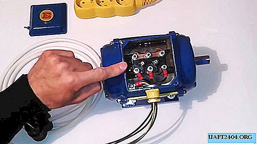
Remove the cover of the motor junction box, gaining access to the jumpers.
Having previously unscrewed the fastening nuts, change the position of the jumpers by changing the connection diagram of the windings to a "triangle". After that, tighten the nuts securely and replace the box cover, noting the connection wires of phases 1, 2 and 3.

Determine the middle winding, cut the core, strip the insulation. Press the ends with the terminal lug, if any, connect the capacitor to the gap.

Conveniently, reliably switch the circuit using terminal pairs. By connecting wires from the motor and the capacitor to the connector, ground, phase and zero are applied from the other end. Gently tightening the terminal screws will ensure reliable electrical contact.
IMPORTANT! The motor has a yellow-green conductor. It is connected to the housing. Connected through the third contacts of the cord plug and socket to ground, it protects against voltage breakdown over the mass of the motor. It is impossible to connect other wires of the electric network to it - only the yellow-green end of the power plug.
The operation of the circuit can be checked by connecting the wire from the capacitor to the phase and turning on the power 220. If all the parts are working, the motor must rotate the rotor in one direction.
Having removed the power, we switch the capacitor to the neutral conductor - the motor rotates in the opposite direction. Choosing the appropriate direction, leave the desired connection constant.

Operational change of the side of rotation to the opposite, will provide a switch connecting the capacitor to phase or zero.
IMPORTANT! Changing direction is allowed only after turning off the power and stopping the rotor completely.
Security
Alteration of the electric motor is connected to 220 volt network operation. Careless handling, carelessness in work is associated with a threat to life or health. Do not leave connections without proper insulation. Restrict outsiders access to the installation until it is completed.


